DIY Wheels for the Losmandy HD Tripod

Just finished today! (Click, and click again, for larger views of each photo.)
I wanted to be able to roll my mount out of the garage, so I looked into getting some kind of system for it. There are a few on the market, but the cheapest one was more expensive than I wanted to pay, so I made my own. They are based on the ScopeRoller system. I only had the photos from their website to go by, but I think I built something very close to theirs, for about one third the cost. I’m not saying their price is too high. It seems like a fine product; and after what it took to make these, I’d say it’s a fine price, too! But I like to make my own things, even when it takes some work.
The legs of the tripod are hollow, and the opening is about 2.36 inches (60mm). According to ScopeRoller, they can vary a bit. I wanted to make an insert that would fit that diameter, so I went looking around Home Depot for something that would work. It needed to be made of something hard and strong enough to be stable, but also something I could work with in my workshop. I don’t have metal-working capability; or not much. What I found was 2-inch, Schedule 40 PVC drain pipe. Pipe measurement is for the inner diameter, so the wall of the pipe added what seemed to be just the right amount. I then went and found a 2-inch dowel to go inside the pipe, and I had what I needed. The four foot dowel plus the two foot pipe cost about $10.
Now I needed wheels, or more accurately, casters: wheels in axled mounts. I wanted them to both swivel and lock, and I needed a way to attach them to the PVC/wooden inserts. I searched and found the ones you see in the photos. The company sells them direct, and also on eBay. I got three of them for $21.90 (plus $16 for shipping).
Construction was pretty straightforward:
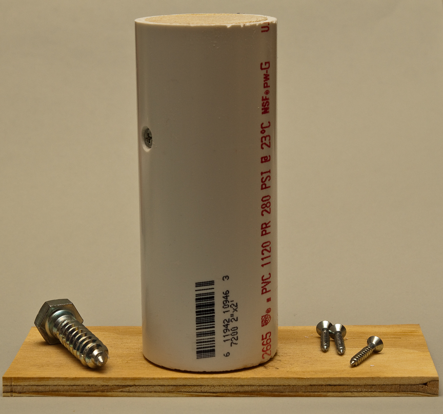
1. I cut three sections, about six inches long, of both the dowel and pipe. The dowel bits fit loosely inside the pipe, so I shaved some long shims off of a piece of pine to fill in the gap enough to get it to stay tightly put. Then I countersunk a couple of wood screws into each section to make them permanent.
2. Now I found out that this was going to be harder than I thought. I brought one of the legs out to my workshop, and tried to put one of the inserts inside. It was close, but the insert was too big. So I got out my palm sander and went at it. PVC is harder than wood. It took about half an hour to 45 minutes per insert. I used 80 grit, then 150, then 320. (When I was finished, it turned out that one leg had a narrower inside than my test leg. It fit with a bit of grease applied, but I should have checked before moving past the point of no return.)
3. After they were thin enough, I cut off the ends of the inserts to match the angle of the tripod legs (30 degrees). I have a power miter saw, but I think a hand saw and miter box would have worked, too.
4. I traced around the oval bottom of the inserts onto some 3/8” plywood, and then penciled in a line about ¼-inch bigger around the tracing. I cut these ovals out with my bandsaw. These are the bits that the bottoms of the legs ride against.
5. I used wood glue to attach the ovals to the bottom of each insert. I didn’t want to have to find a way to clamp such an awkward angle, so I spread some glue on each wood surface, let it sit for a minute or two, then put a bit more glue on one piece, and squeezed them together. After holding them together with my hands for about a minute, they stuck well enough that I could set each piece in a cup — with the oval horizontal — to dry.

6. I clamped each piece in a wooden handscrew clamp, so I could position it for perpendicular drilling under my drill press. I drilled three pilot holes and countersunk three ¾” wood screws to further bind the ovals. After screwing in the wood screws, I then put a 3/8” hole in the center, for the 2” long, ½” lag bolts that hold the casters to each insert.

7. I used black oil paint on the parts of the insert that will be seen, let it dry overnight, and then put three coats of polyurethane over all exposed wood surfaces, even those that will be inside the legs.
8. In order to screw in the lag bolts, the wheels had to be removed first. This was easily done with a couple of wrenches.


Once finished, I tested the casters on my mount. I have not been able to actually use it under the stars yet, but it seems fairly solid. They also move very smoothly. I don’t expect this to be stable enough for long-exposure astrophotography, because there is a bit of play in the casters. But, with the weight of the mount on top of them, they are actually stiffer than I thought they might be. I do hope to use them for planetary (video) work, and visual.

Finished!
The casters add about 4-3/8ths inches to the height of the mount.
